

Vehicle Suspension Design
- Dec 12, 2022
- 4 min read
Updated: Mar 21, 2023

Creating a well-performing four wheeled vehicle’s suspension is a balancing act of component stiffness, component strength, component weight, and assembly geometry.
A vehicle’s suspension is intended to keep the cabin and its occupants supported safely and steadily during travel. At low speeds, high speeds, and changes of speed and direction the cabin of the vehicle should be limited in the amount of jerking and bouncing it experiences. Considering the horse drawn wagons of our ancestors, their vehicle suspension geometry wasn’t much more than simple axles and wheels attached directly to the cabin. The occupant or driver felt every jolt that the wheels experienced from contact with the ground. The wheels had no significant ability to absorb input forces from hitting objects or accommodate changes in ground elevation along their path.
While a vehicle’s suspension design can be approached from several different ways, the general idea is to either start with a bodywork and chassis design, determine the vehicle’s wheelbase and track, and then add the suspension and wheels and tires. Or, conversely, one may determine the vehicle’s wheelbase and track, start with the wheels and tires, and then work the design inboard from there by adding suspension components and the chassis and bodywork. The goal is to best control the orientation of the wheel and tire assembly orientation while the vehicle’s chassis experiences, ride height changes, roll changes, and steering inputs.
If given the freedom, we prefer to use the approach of starting with the wheelbase and track dimensions, adding the wheels and tires, and then working on the kinematics/geometry of the suspension and steering. Then the chassis can be developed and arranged efficiently to support the input loads from the wheel & tire assemblies during operation. The chassis and bodywork are then refined to ensure there are adequate clearances to frame rails, chassis tubes, and body panels.
The work for the vehicle’s suspension geometry is first done without fully understanding the magnitude of forces involved. The engineer or designer will know the fundamental location and direction of forces to be supported, but first they are working with knowledge that the wheel and tire assemblies will have a desired and prescribed range of vertical travel and steering angle. This is to accommodate road and terrain inputs (bumps, rocks, holes, etc.) and provide a sufficient turning radius for the size of vehicle. This area of physics is called kinematics and it’s the study of a mechanical system’s motion without directly considering the forces involved.
Let’s consider a four wheeled vehicle where the front axle wheels are steered and the rear axle wheels are not. The front wheels’ orientations must be considered during:
• minimum to maximum steering angles
• minimum to maximum vertical travels
There are an infinite number of suspension link kinematic arrangements to evaluate that will control the wheel orientations during operation. Many suspension and steering variants should be considered because each design change in the suspension or steering may affect other desirable characteristics.
Below is a drawing of a typical front suspension model in an offset view.

Next, is a drawing of the front suspension model in a rear end view.
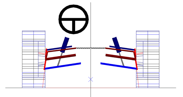
And below is a drawing of the front suspension model in a rear end view during a left hand turn with chassis roll.

Visual models, such as these, help in understanding the relationship of steering linkages, lower suspension links, and upper suspension links. The models also help understand the effects on wheel orientations during ride height changes, chassis roll changes, and steering inputs.
The interplay of these links has dramatic effects on the drivability of the vehicle and the comfort level for the operator and its occupants. For example, the link geometry can affect:
• the amount of steering effort required to turn the steering wheel
• the share of load a road wheel and tire assembly experiences when making a turn
• how tight a turn a vehicle can make
• how much of the tire tread stays in contact with the ground during steering and vertical suspension travel
• how easily the vehicle stays pointed straight head while travelling
Values such as scrub radius, caster trail, camber change, Ackermann, toe change, etc. are considered with each variation in suspension geometry. Developed methods are then used to carefully assess these values and determine the best suspension geometry for controlling a vehicle’s response to forces from braking, cornering, accelerating, and road bumps and holes.
For the specified performance goals of the vehicle, the next steps then taken are in engineering the individual components to carry those loads. This stage of automotive suspension design explores further the realms of material science, mechanical behavior of materials, and dynamics.
CAD (computer aided design) is used to engineer the specific suspension links required for supporting the vehicle’s chassis loads and connecting them to the wheel and tire assemblies. Also, it can be used to simulate the assembly of suspension, steering, and chassis systems and ensure all components operate and package as expected. CAD techniques are used to illustrate the suspension geometry in different orientations.
Contact us at Convergence Design Services for all your electric vehicle designs


